Am radio receiver circuit pdf
Superheterodyne receiver circuit blocks There are some key circuit blocks that form the basic superheterodyne receiver. Although more complicated receivers can be made, the basic circuit is widely used – further blocks can add improved performance or additional functionality and their operation within the whole receiver is normally easy to determine once the basic block diagram is understood.
AM radio receiver datasheet, cross reference, circuit and application notes in pdf format.
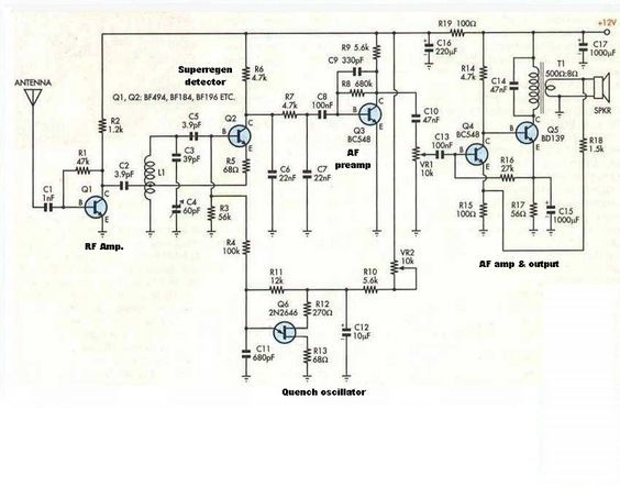
This is the circuit diagram of mini AM Radio receiver. All general purpose transistors should work in this circuit, you can use BC549 transistors for this circuit. The circuit use a compact three transistor, regenerative receiver with fixed feedback. It is similar in principle to the ZN414 radio IC which is now replaced by the MK484. The design is simple and sensitivity and selectivity of the
Design of integrated, low power, radio receivers in bicmos technologies by… building block ics for radio receivers… since circuits for am-
The earliest radio receiver was simply made with an antenna, a detector and earphones. The detector serves the purpose of extracting the audio from the modulated carrier and often does so by allowing current only in one direction. The diode is the simplest device that allows current in one direction. However, only allowing the positive edges of the modulated signal to pass through to the audio
18/09/2008 · I’d like to design a simple AM radio receiver. It should be able to drive a small speaker, and the antenna shouldn’t have to be longer than a meter. It should be able to drive a small speaker, and the antenna shouldn’t have to be longer than a meter.
AM Receiver Prelab In this experiment you will use what you learned in your previous lab sessions to make an AM receiver circuit. You will construct an envelope detector AM receiver. P1) Introduction One of the simplest schemes for wireless communication is Amplitude Modulation (AM). Modulation is necessary for a number of reasons: • The attenuation of the channel, i.e. air, is high for low
This circuit is not only just limited to AM broadcast radio (535 to 1605 kHz) and with a little modification to the inductor coils, could achieve tuning below 535 kHz or even higher for shortwave reception.
The receiver input circuit is designed to efficiently transfer power from the antenna to the receiver while developing a minimum of noise within the receiver itself. Local Oscillator and Mixer The local oscillator (LO) and mixer perform the important task of converting the desired radio frequency signals down to the range of audio frequencies. The local oscillator generates a sinusoidal
When it comes to making an FM receiver it’s always thought to be a complex design, however the one transistor simple FM receiver circuit explained here simply shows that it isn’t the case after all.
Figure 7 shows the circuit you will build for your radio receiver. This circuit consists of four This circuit consists of four basic sections: a “tank circuit”, a …
This AM receiver consists of a TDA7000 single-chip FM receiver (U1) as the main radio component, and an LM386 chip for low-voltage audio-power amplifier (U2) circuit.
Tuned circuits are separated by the radio frequency (RF) amplifier stages and the last tuned circuit feeds the AM detector stage. This receiver belongs to an era before the introduction of the screen grid valve and it is interesting to observe the grid-plate capacity neutralisation applied to the triode RF amplifiers to maintain amplifier stability. In these early receivers, the individual
October 1990 2 Philips Semiconductors Product specification 1-chip AM radio TEA5551T GENERAL DESCRIPTION The TEA5551T is a 1-chip monolithic integrated radio circuit which is designed for use as a pocket receiver with
If I use this circuit with a loop antenna of any appreciable size, I can also pick up 4RK up in Rockhampton (I live in Brisbane myself,) and 531 AM, a NSW radio station down near Coffs Harbour – quite a few kilometres in either direction.
AM Receiver Circuit. P. Marian. AM radio; radio receivers; Application: A small, simple AM receiver project with only 3 transistors. This circuit can pick up medium wave stations in your area. Description: It can use general purpose transistors, and in this example there are 3 BC109C transistors. The schematic and BOM show a 200µH inductor and a trimmer capacitor 150-500pF, though these parts
AM radio receivers How AM radio receivers work, An AM Radio Realized with Only Discrete Bipolar Transistors, pdf file AM SUPERHETERODYNE RECEIVERS IF section, AM receivers, diode detector AM transmitters and receivers AM communication, AM transmitters and receivers, pdf file
15/05/2013 · This video shows the complete AM Radio Receiver Circuit built on a Veroboard. It uses a simple TA7642 Radio IC as radio receiver and a TBA820M 1.2W audio amplifier IC. Powered from a …
AM Radio Receiver built on Veroboard (completed circuit
www.epemag3.com
IC MK484 AM RADIO RECEIVER TO92 Be the first to know about our newest products, specials and promotions:
For the radio experimenter it is a very practical outfit. In building this portable, the first consideration was what circuit to use. Above- I- Circuit for 2 -tube all -wave receiver. condenser. No screen grid resistor is used inasmuch as the B battery has a 221/0 v tap.
In an AM receiver, the gain of every circuit counts, since audio level out is a direct function of RF input. In an FM receiver, therefore, sensitivity problems will usually be in the RF section of the
19/06/2009 · Oye buddys.. Here’s a very simple AM Radio circuit I’ve designed couple of years ago. Don’t know whether anybody listen to AM stations anymore.
From the mid 1970’s onwards, if you wanted to build a simple AM radio, chances are the circuit you would use was based around the ZN414. This TRF radio IC, well known to European and Australasian constructors of radio receivers, was developed in the early 1970’s by Ferranti in the UK.
AM TRANSISTOR RADIO RECEIVER datasheet, cross reference, circuit and application notes in pdf format.
6/10/2017 · Do you want a simple DIY radio in order to learn how AM and FM works? It would be best to choose one alone, i.e. AM or FM but not both. It would be best to choose one alone, i.e. AM …
CHAPTER 4 RF/IF CIRCUITS INTRODUCTION 4.1 SECTION 4.1: MIXERS 4.3 cases the receivers and transmitters are a variation on the superheterodyne radio shown in Figure 4.1 for the receiver and Figure 4.2 for the transmitter. Figure 4.1: Basic Superheterodyne Radio Receiver Figure 4.2: Basic Superheterodyne Radio Transmitter LO LO IF AGC RF DEMOD LO LO RF IF MOD. BASIC LINEAR …
This is the circuit diagram of mini AM Radio receiver. All general purpose transistors should work in this circuit, you can use BC549 transistors for this circuit. The circuit use a compact three transistor, regenerative receiver with fixed feedback.
Miniproject: AM Radio 1 Objective Until now, the labs have focused primarily on characterizing circuits; you’ve been asked to analyze, build, and characterizea number of different amplifiers and biasing circuits, but we’ve only given you small amounts of design (e.g. picking resistors or bias voltages). In this miniproject, we want to give you the freedom to design an amplifier from the
BOYS BOOK 22 M MFD. ANTENNA COIL OF RADIO AND TUE VOLTS @ 002 CAP. FOUR PRACTICAL RADIO RECEIVERS tion of how the pentode performs in this circuit requires a brief
The TDA 1072AT integrated AM receiver circuit performs the active and part of the filtering functions of an AM radio receiver. It is intended for use in mains-fed home receivers and car radios.
The following circuit was taken from an old electronic book, it is indeed a very nice little two transistor radio receiver circuit which utilizes very few components yet is able to produce output over a loudspeaker and not just over headphones.
processing (DSP) circuit, or a digital to analog converter PAC), where the input voltage range is typically 1 mV to 1 V. For example, in a digital PCS telephone receiver the input signal is demodulated to
SR-1 – 4 INTRODUCTION TO THE SR-1 The SR-1 is a single-conversion superheterodyne receiver designed specifically for listening to AM broadcasting stations in the range of 4 to 10 Mhz.
Making a simple AM Radio First experiences with radio frequency circuits. All the other projects I have made so far have been digital and microcontroller based, with the one exception to this being the Nutclough amplifier, which was assembled from a kit.
AM TRANSISTOR RADIO RECEIVER datasheet & applicatoin notes
– project blue sky inc v australian broadcasting authority pdf
AM Receiver Circuit Exchange International (CXI)
AM Radio Receiver Circuit Schematic
AM receiver circuit Digi-Key
AM Radio Receiver Electronic Circuit Diagram
MK484 AM Radio receiver TO-92 Jaycar Electronics
Miniproject AM Radio University of California Berkeley
AM/FM Receiver Radio All About Circuits
1-chip AM radio SHF Micro
– AM Radio Receiver Circuit Wiring Diagrams
Designing a simple AM radio receiver Electronics Forum

4-10 MHz SHORTWAVE RADIO
MK484 AM Radio receiver TO-92 Jaycar Electronics
AM Receiver Circuit Electroschematics
AM TRANSISTOR RADIO RECEIVER datasheet, cross reference, circuit and application notes in pdf format.
19/06/2009 · Oye buddys.. Here’s a very simple AM Radio circuit I’ve designed couple of years ago. Don’t know whether anybody listen to AM stations anymore.
SR-1 – 4 INTRODUCTION TO THE SR-1 The SR-1 is a single-conversion superheterodyne receiver designed specifically for listening to AM broadcasting stations in the range of 4 to 10 Mhz.
This circuit is not only just limited to AM broadcast radio (535 to 1605 kHz) and with a little modification to the inductor coils, could achieve tuning below 535 kHz or even higher for shortwave reception.
AM radio receiver datasheet, cross reference, circuit and application notes in pdf format.
The earliest radio receiver was simply made with an antenna, a detector and earphones. The detector serves the purpose of extracting the audio from the modulated carrier and often does so by allowing current only in one direction. The diode is the simplest device that allows current in one direction. However, only allowing the positive edges of the modulated signal to pass through to the audio
AM radio receivers How AM radio receivers work, An AM Radio Realized with Only Discrete Bipolar Transistors, pdf file AM SUPERHETERODYNE RECEIVERS IF section, AM receivers, diode detector AM transmitters and receivers AM communication, AM transmitters and receivers, pdf file
Tuned circuits are separated by the radio frequency (RF) amplifier stages and the last tuned circuit feeds the AM detector stage. This receiver belongs to an era before the introduction of the screen grid valve and it is interesting to observe the grid-plate capacity neutralisation applied to the triode RF amplifiers to maintain amplifier stability. In these early receivers, the individual
CHAPTER 4 RF/IF CIRCUITS INTRODUCTION 4.1 SECTION 4.1: MIXERS 4.3 cases the receivers and transmitters are a variation on the superheterodyne radio shown in Figure 4.1 for the receiver and Figure 4.2 for the transmitter. Figure 4.1: Basic Superheterodyne Radio Receiver Figure 4.2: Basic Superheterodyne Radio Transmitter LO LO IF AGC RF DEMOD LO LO RF IF MOD. BASIC LINEAR …
15/05/2013 · This video shows the complete AM Radio Receiver Circuit built on a Veroboard. It uses a simple TA7642 Radio IC as radio receiver and a TBA820M 1.2W audio amplifier IC. Powered from a …
When it comes to making an FM receiver it’s always thought to be a complex design, however the one transistor simple FM receiver circuit explained here simply shows that it isn’t the case after all.
For the radio experimenter it is a very practical outfit. In building this portable, the first consideration was what circuit to use. Above- I- Circuit for 2 -tube all -wave receiver. condenser. No screen grid resistor is used inasmuch as the B battery has a 221/0 v tap.
Superheterodyne receiver circuit blocks There are some key circuit blocks that form the basic superheterodyne receiver. Although more complicated receivers can be made, the basic circuit is widely used – further blocks can add improved performance or additional functionality and their operation within the whole receiver is normally easy to determine once the basic block diagram is understood.
In an AM receiver, the gain of every circuit counts, since audio level out is a direct function of RF input. In an FM receiver, therefore, sensitivity problems will usually be in the RF section of the
IC MK484 AM RADIO RECEIVER TO92 Be the first to know about our newest products, specials and promotions:
AM Radio Receiver built on Veroboard (completed circuit
1-chip AM radio SHF Micro
This circuit is not only just limited to AM broadcast radio (535 to 1605 kHz) and with a little modification to the inductor coils, could achieve tuning below 535 kHz or even higher for shortwave reception.
Tuned circuits are separated by the radio frequency (RF) amplifier stages and the last tuned circuit feeds the AM detector stage. This receiver belongs to an era before the introduction of the screen grid valve and it is interesting to observe the grid-plate capacity neutralisation applied to the triode RF amplifiers to maintain amplifier stability. In these early receivers, the individual
From the mid 1970’s onwards, if you wanted to build a simple AM radio, chances are the circuit you would use was based around the ZN414. This TRF radio IC, well known to European and Australasian constructors of radio receivers, was developed in the early 1970’s by Ferranti in the UK.
Design of integrated, low power, radio receivers in bicmos technologies by… building block ics for radio receivers… since circuits for am-
IC MK484 AM RADIO RECEIVER TO92 Be the first to know about our newest products, specials and promotions:
Figure 7 shows the circuit you will build for your radio receiver. This circuit consists of four This circuit consists of four basic sections: a “tank circuit”, a …
In an AM receiver, the gain of every circuit counts, since audio level out is a direct function of RF input. In an FM receiver, therefore, sensitivity problems will usually be in the RF section of the
The receiver input circuit is designed to efficiently transfer power from the antenna to the receiver while developing a minimum of noise within the receiver itself. Local Oscillator and Mixer The local oscillator (LO) and mixer perform the important task of converting the desired radio frequency signals down to the range of audio frequencies. The local oscillator generates a sinusoidal
Superheterodyne receiver circuit blocks There are some key circuit blocks that form the basic superheterodyne receiver. Although more complicated receivers can be made, the basic circuit is widely used – further blocks can add improved performance or additional functionality and their operation within the whole receiver is normally easy to determine once the basic block diagram is understood.
October 1990 2 Philips Semiconductors Product specification 1-chip AM radio TEA5551T GENERAL DESCRIPTION The TEA5551T is a 1-chip monolithic integrated radio circuit which is designed for use as a pocket receiver with
For the radio experimenter it is a very practical outfit. In building this portable, the first consideration was what circuit to use. Above- I- Circuit for 2 -tube all -wave receiver. condenser. No screen grid resistor is used inasmuch as the B battery has a 221/0 v tap.
Miniproject: AM Radio 1 Objective Until now, the labs have focused primarily on characterizing circuits; you’ve been asked to analyze, build, and characterizea number of different amplifiers and biasing circuits, but we’ve only given you small amounts of design (e.g. picking resistors or bias voltages). In this miniproject, we want to give you the freedom to design an amplifier from the
TROUBLESHOOTING RECEIVERS wb6nvh.com
TDA1072A datasheet(2/20 Pages) PHILIPS AM receiver circuit
Tuned circuits are separated by the radio frequency (RF) amplifier stages and the last tuned circuit feeds the AM detector stage. This receiver belongs to an era before the introduction of the screen grid valve and it is interesting to observe the grid-plate capacity neutralisation applied to the triode RF amplifiers to maintain amplifier stability. In these early receivers, the individual
Design of integrated, low power, radio receivers in bicmos technologies by… building block ics for radio receivers… since circuits for am-
This is the circuit diagram of mini AM Radio receiver. All general purpose transistors should work in this circuit, you can use BC549 transistors for this circuit. The circuit use a compact three transistor, regenerative receiver with fixed feedback.
CHAPTER 4 RF/IF CIRCUITS INTRODUCTION 4.1 SECTION 4.1: MIXERS 4.3 cases the receivers and transmitters are a variation on the superheterodyne radio shown in Figure 4.1 for the receiver and Figure 4.2 for the transmitter. Figure 4.1: Basic Superheterodyne Radio Receiver Figure 4.2: Basic Superheterodyne Radio Transmitter LO LO IF AGC RF DEMOD LO LO RF IF MOD. BASIC LINEAR …
AM Receiver Prelab In this experiment you will use what you learned in your previous lab sessions to make an AM receiver circuit. You will construct an envelope detector AM receiver. P1) Introduction One of the simplest schemes for wireless communication is Amplitude Modulation (AM). Modulation is necessary for a number of reasons: • The attenuation of the channel, i.e. air, is high for low
This circuit is not only just limited to AM broadcast radio (535 to 1605 kHz) and with a little modification to the inductor coils, could achieve tuning below 535 kHz or even higher for shortwave reception.
Figure 7 shows the circuit you will build for your radio receiver. This circuit consists of four This circuit consists of four basic sections: a “tank circuit”, a …
The earliest radio receiver was simply made with an antenna, a detector and earphones. The detector serves the purpose of extracting the audio from the modulated carrier and often does so by allowing current only in one direction. The diode is the simplest device that allows current in one direction. However, only allowing the positive edges of the modulated signal to pass through to the audio
Miniproject AM Radio University of California Berkeley
AM Radio Receiver Schematic Design – circuitdiagram.net
AM Radio Receiver Circuit Wiring Diagrams
18/09/2008 · I’d like to design a simple AM radio receiver. It should be able to drive a small speaker, and the antenna shouldn’t have to be longer than a meter. It should be able to drive a small speaker, and the antenna shouldn’t have to be longer than a meter.
Simple AM Radio Receiver Electronics Forum (Circuits
http://www.epemag3.com
Making a simple AM Radio rs-online.com
The receiver input circuit is designed to efficiently transfer power from the antenna to the receiver while developing a minimum of noise within the receiver itself. Local Oscillator and Mixer The local oscillator (LO) and mixer perform the important task of converting the desired radio frequency signals down to the range of audio frequencies. The local oscillator generates a sinusoidal
AM/FM Receiver Radio All About Circuits
This is the circuit diagram of mini AM Radio receiver. All general purpose transistors should work in this circuit, you can use BC549 transistors for this circuit. The circuit use a compact three transistor, regenerative receiver with fixed feedback.
AM/FM Receiver Radio All About Circuits
Making a simple AM Radio First experiences with radio frequency circuits. All the other projects I have made so far have been digital and microcontroller based, with the one exception to this being the Nutclough amplifier, which was assembled from a kit.
MK484 AM Radio receiver TO-92 Jaycar Electronics
Miniproject AM Radio University of California Berkeley
Making a simple AM Radio rs-online.com
This is the circuit diagram of mini AM Radio receiver. All general purpose transistors should work in this circuit, you can use BC549 transistors for this circuit. The circuit use a compact three transistor, regenerative receiver with fixed feedback. It is similar in principle to the ZN414 radio IC which is now replaced by the MK484. The design is simple and sensitivity and selectivity of the
MK484 AM Radio receiver TO-92 Jaycar Electronics
http://www.epemag3.com
AM radio receiver datasheet & applicatoin notes
Design of integrated, low power, radio receivers in bicmos technologies by… building block ics for radio receivers… since circuits for am-
4-10 MHz SHORTWAVE RADIO
This AM receiver consists of a TDA7000 single-chip FM receiver (U1) as the main radio component, and an LM386 chip for low-voltage audio-power amplifier (U2) circuit.
AM receiver circuit Digi-Key